contact us: 1-877-755-weld(9353) DEALERS WANTED | Terms & Policy

Wednesday, July 29, 2009

Residual Stress

Residual stress is a process-induced stress, frozen in a molded part. It can be either flow-induced or thermal-induced. Residual stresses affect a part similarly to externally applied stresses. If they are strong enough to overcome the structural integrity of the part, the part will warp upon ejection, or later crack, when external service load is applied. Residual stresses are the main cause of part shrinkage and warpage. The process conditions and design elements that reduce shear stress during cavity filling will help to reduce flow-induced residual stress. Likewise, those that promote sufficient packing and uniform mold cooling will reduce thermal-induced residual stress. For fiber-filled materials, those process conditions that promote uniform mechanical properties will reduce thermal-induced residual stress.

Flow-induced residual stress
Unstressed, long-chain polymer molecules tend to conform to a random-coil state of equilibrium at temperatures higher than the melt temperature (i.e., in a molten state). During processing the molecules orient in the direction of flow, as the polymer is sheared and elongated. If solidification occurs before the polymer molecules are fully relaxed to their state of equilibrium, molecular orientation is locked within the molded part. This type of frozen-in stressed state is often referred to as flow-induced residual stress. Because of the stretched molecular orientation in the direction of flow, it introduces anisotropic, non-uniform shrinkage and mechanical properties in the directions parallel and perpendicular to the direction of flow.

Reducing flow-induced residual stress
Process conditions that reduce the shear stress in the melt will reduce the level of flow-induced residual stresses. In general, flow-induced residual stress is one order of magnitude smaller than the thermal-induced residual stress.

  • higher melt temperature

  • higher mold-wall temperature

  • longer fill time (lower melt velocity)

  • decreased packing pressure

  • shorter flow path.

Labels: , ,

Monday, July 27, 2009

Unoffical Weld Symbols

Labels: ,

Thursday, July 23, 2009

Acetylene Cutting and Welding Safe Operating Procedures


  • Cylinders, cylinder valves, couplings, regulators, hose, and apparatus must be kept
    free from oily or greasy substances.
  • Oxygen cylinders or apparatus must not be handled with oily hands or gloves.
  • A jet of oxygen must never be permitted to strike an oily surface, greasy clothes, or
    enter a fuel oil or other storage tank.
  • When transporting cylinders by a crane or derrick, a cradle, boat, or suitable platform
    shall be used. Slings or electric magnets shall not be used for this purpose.
  • Valve-protection caps, where cylinder is designed to accept a cap, must always be in
    place.
  • Cylinders must not be dropped or struck or permitted to strike each other violently.
    Valve-protection caps must not be used for lifting cylinders from one vertical position
    to another.
  • Bars must not be used under valves or valve-protection caps to pry cylinders loose
    when frozen to the ground or otherwise fixed; the use of warm (not boiling) water is
    recommended.
  • Valve-protection caps are designed to protect cylinder valves from damage.
  • Unless cylinders are secured on a special truck, regulators must be removed and
    valve-protection caps, when provided for, must be put in place before cylinders are
    moved.
  • Cylinders not having fixed hand wheels must have keys, handles, or nonadjustable
    wrenches on valve stems while these cylinders are in service. In multiple cylinder
    installations
    only one key or handle is required for each manifold.
  • Cylinder valves must be closed before moving cylinders.
  • Cylinder valves must be closed when work is finished.

Labels: , ,

Wednesday, July 22, 2009

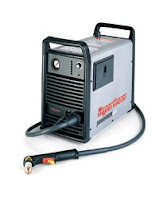
Hypertherm Powermax 600 Plasma Cutter

Plasma Cutter
Uses

Cutting of metals
Materials

* Aluminum
* Mild steel
* Stainless Steel

Device Specifications

* Rated Output: 20A-40A
* Rated Output at 50% Duty Cycle: 40 A, 140V
* Rated Open-Circuit Voltage: 300V
* Dimensions: 22.1" L x 13.6" W x 21" H
* Max Cutting Capacity: 5/8" @ 50% Duty Cycle
* Gas Type: Air or Nitrogen

Labels: ,

Friday, July 17, 2009

Fillet Welded Joints


A typical fillet welded joint is illustrated. It connects two components, one of which is conveniently regarded as the loaded member - as all loads on it are known - the other is the support or reaction member. Clearly the loads are transmitted through the joint before being absorbed in the support.

A run may be three -dimensional however the majority of practical runs are two -dimensional and lie in a weld plane like the cantilever's joint here. We consider only such two -dimensional runs, the centroids of which must also lie in the weld plane. It is convenient to erect a Cartesian system at the centroid G, and to designate the x-y plane as the weld plane as shown at ( a) below.


In general the resultant load on the joint is a force F = [ Fx Fy Fz ]' through the centroid of the linear run, together with a moment M = [ Mx My Mz ]' whose components are given by the RH Rule, ( b). For the cantilever above, this resultant would be found by moving the sole force to act through the centroid, and introducing the moment corresponding to the force multiplied by the distance transverse to the force's line of action between the point of load application and the centroid.

This load is equilibrated by a force distributed along the length L of the run as indicated in ( c). By virtue of the stresses in the weld, each element of run δL contributes an elemental force q.δL towards equilibrium. q is a force intensity ; it is a vector force -per -unit -length and except in simple cases varies in magnitude and direction around the run.

Conceptually, force intensity is not too different from stress, which is a force -per -unit -area, that is δF = q δL = σ δA. Force intensity is also similar to the bending moment in a beam: both are stress resultants - of stresses in the weld throat and in the beam's cross-section respectively - and both vary in general along a linear path - the weld run and the beam axis.

For the majority of beams the bending moment is easily found in terms of the loads using statics. In the case of a fillet weld however, correlating the intensity q with the load F, M is less straightforward since the arrangement is statically indeterminate.

Two techniques for this correlation (having the same theoretical foundation) are presented below. The first traditional approach is based on recasting the building block stress equations for bending etc. in terms of force intensity rather than of stress. This approach though simple has limitations which in some situations requires the more general second technique, the unified approach.

Source: http://www.mech.uwa.edu.au/DANotes/welds/fillets/fillets.html

Labels: ,

Tuesday, July 14, 2009

Welding Women

Labels: ,

Friday, July 10, 2009

What Does a Metal Fabricator/Welder Do?


A metal fabricator has to be talented to interpret engineering drawings and then exactly cut steel plates into the required shapes. They must then weld them into the structure according to the drawings.

Metal Fabricators must learn to read engineering drawings, use geometric progress methods and metal forming techniques. They must also be able to use computers in making metal products, and have a inclusive knowledge of a range of industrial welding and joining processes to produce the required items.

Labels: , ,

Wednesday, July 8, 2009

Welding Fumes Sampling


The potential hazards of welding operations include metal fumes, toxic gases, and ultraviolet and infrared radiation. Fume particles are formed from vaporization of molten metal. They are very fine in size, generally one micron or smaller, and may join together to form larger particles. Fumes can be sampled by drawing air through a special filter at a controlled rate. The adverse health effects of overexposure to welding fumes and gases include chronic or acute systemic poisoning, metal fume fever (a short-term painful ailment with symptoms of fever and chills), pneumoconiosis (lung disease due to accumulation of mineral or metallic particles), and irritation of the respiratory tract.

The welding fumes produced at welding operations depend primarily on the composition of the metals being welded and the welding rods. When the base metal is iron or steel, with welding rods of similar composition the main component of the fume will be iron oxide. When welding on stainless steel, fumes containing nickel and chromium may be produced. Welding on plated, galvanized, or painted metals may generate fumes containing cadmium, zinc oxide, or lead. In addition, welding rods can generate fluoride in the fume as well as free silica, depending on the composition of the welding rod coating. In summary, welding processes may generate many different metal fumes and other toxic components. It is important that the hazards of a welding operation be evaluated properly. Toxic gases that arise in welding include carbon monoxide, nitrogen dioxides, and ozone. If welding or cutting operations are conducted in the presence of chlorinated hydrocarbons, such as the form of solvents either on the metals or in the air, hazardous concentrations of phosgene and hydrogen chloride, which are highly toxic irritant gases, may be produced.

In addition to the health hazards of metal fumes and toxic gases, welding operations involve the hazard of burns from flame, arc, molten metal, and heated surfaces and also that of metal splatter. Welding operations in general require face, neck and eye protection for the welder -- against sparks, splatter of molten metal, and the radiations (ultraviolet, infrared, and intense visible) of the arc or flame. Normally this means that a welder will wear a welding hood, or helmet, though in some cases gas welding may properly be done with adequate goggles, gloves, and other protective clothing of neck and arms. When personal respiratory protection is required, this may be provided by a supplied-air welding hood or when the components and concentration of the fume are known, by a filter-type respirator with filter for protection against fumes. It is preferable, of course, that adequate ventilation be provided so as to make the use of respirators unnecessary.

When sampling for welding fumes, the inspector will use a filter-cassette placed on the collar or shoulder so that it is beneath the helmet when the helmet is placed down. the sampling pump is fastened to the belt. Samples may be full shift or short-term. Short-term samples may be taken to evaluate toxic components which have short-term limits. In addition, the inspector may sample for toxic gases such as ozone, nitrogen oxides, or phosgene. It is important that the welder carry out the welding operation in a normal way, so that an accurate evaluation of the exposure can be made. The inspector will attach and remove the filter cassette and pump as required.

Normally, good local or general ventilation is required to control exposures to the metal fumes and gases of welding operations. The most effective control is local exhaust ventilation in which an exhaust hood is placed near the welding arc or flame, and the contaminants are drawn away from the welder's breathing zone. The system may consist of moveable exhaust hoods, flexible and stationary ducts, a powered fan, and a fume or dust collector. Exhausted air should be discharged to the outdoors, if possible, it is important that, during the welding operation, the exhaust hoods are placed or set so that welding fumes are not drawn across the worker's face or into the breathing zone. Good general ventilation should be provided. Welding in confined spaces such as tanks, cabs of mobile equipment, and large shovels may be especially hazardous and requires additional ventilation.

Labels: ,

Tuesday, July 7, 2009

Rule Of Thumb Fillet Weld Sizes

Labels: , ,

Monday, July 6, 2009

Arc Welding Tips, Tricks and Techniques

Labels: ,

Friday, July 3, 2009

Resistance Spot Welding

Labels: , ,

Thursday, July 2, 2009

Welding Underwater

Labels: , ,

Wednesday, July 1, 2009

Welding Robot

Labels: , ,