contact us: 1-877-755-weld(9353) DEALERS WANTED | Terms & Policy

Wednesday, September 23, 2009

Features of Fusion Welded Joint


A typical fusion weld joint consists of fusion zone, weld interface, heat affected zone and unaffected base metal zone.

  • Fusion zone: a mixture of filler metal and base metal melted together homogeneously due to convection as in casting. Epitaxial grain growth (casting)

  • Weld interface – a narrow boundary immediately solidified after melting.

  • Heat Affected Zone (HAZ) – below melting but substantial microstructural change even though the same chemical composition as base metal (heat treating) – usually degradation in mechanical properties

  • Unaffected base metal zone (UBMZ) – high residual stress


  • Welders | Hobart | Lincoln | Miller | Tig | Mig

    Labels: ,

    Tuesday, September 22, 2009

    Welding on Aluminum Casting


    • Grind off sand from rough castings. Smooth in areas to be welded. There are grinding wheels for 4-1/2” and larger grinders made specifically to grind aluminum.

    • Castings that are dirty or oily need special care. You can plasma cut a crack out if possible. This cleans out the oil in the crack. Drill holes at the ends of cracks or they will continue on after the repair is made. Clean the surface with alcohol or similar cleaner. Carefully heat the area with a oxy-acetylene torch to cook out the oil. Go over the crack with the TIG torch with low heat. Use a small tungsten electrode. These are called cleanup passes. Do not add welding rod. Every time you go over aluminum it should get cleaner. You will see black discolored aluminum in the beginning. Weld; grind; weld; grind. Eventually the aluminum will be shiny silver color, then you can weld with rod and larger tungsten.

    • You can use sanding discs on aluminum to metal finish; spray WD40 on the disc and the part to keep it from loading up.

    Labels: ,

    Monday, September 21, 2009

    Magnetic Rotating Arc Welding

    Developed in the 1970's, magnetic rotating arc welding is also known as magnetarc welding or magnetically impelled arc butt (MIAB) welding . It is defined as "an arc welding process in which an arc is created between the butted ends of tubes and propelled around the weld joint by a magnetic field, followed by an upsetting operation." The procedure is a mixture of arc and forge welding with a gas shielding operation added on. This method of welding by clamping the parts to be joined into the machine. Next, the two pieces are pushed together and electricity is applied to them. As they are separated, an arc is started. When the arc is established, a magnetic coil around the weld repels the arc, which pushes it around the perimeter of the piece. The arc runs around the piece at a speed close to 50 meters a second. At this speed the arc looks as though it is a circle of light between the pieces. After the arc has run around the piece for a determined amount of time, the two pieces are pressed together to join them .

    This process is now very popular in mass production situations. The entire system is fast, can be automated, and requires less energy than other types of welding. The parts do not need to be cylindrical and the welds are repeatable with high quality and little deformities. Also, this welding does not expel as much metal as does other forms of welding, which makes MIAB welding more efficient. The drawback comes from the fact that the arc only heats the edges of the pieces, not the middle. This means that only a certain thickness of metal can be welded in this fashion and that solid pieces of metal cannot be joined.

    Labels: ,

    Arc Welding and Related Methods

    Labels: , , ,

    Friday, September 18, 2009

    Atomic Hydrogen Welding

    Arc Welding

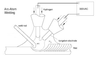
    This process involves injecting hydrogen into extreme heat in the arc, the temperature makes the hydrogen gas (H2) and breaks it down into its simplest form, which would be two hydrogen atoms. The arc is formed between two tungsten electrodes, not between the metal workpiece and the electrodes as in other types of arc welding. This process absorbs energy away from the arc, but gives it back as the hydrogen recombines as it contacts the metal work surface. The procedure uses the heat from the reaction to heat the metal. The temperature of the flame reaches 3700°C and can then be used for welding . The arc in this case does not have much of an effect on the weld except it can increase the temperature some as the electrodes get closer to the weld pool. The transformer for this operation is generally around 300 volts, so caution is needed.

    For years hydrogen arc welding was used for hard-to-weld metals such as nickel-base alloys and high alloy steels. The hydrogen used helped reduce gas bubbles in the weld, which provided a seam with fewer pores. This makes a much stronger weld because more metal is holding the pieces together. The hydrogen is also good due to the fact that other gases cannot enter the weld pool because it is protected by the stream of hydrogen gas. This process has been almost overshadowed by inert-gas arc welding.

    Labels: ,

    Wednesday, September 16, 2009

    Air Plasma Cutting

    Air Plasma Cutting Advantages
    • 3 to 5 times faster than conventional gas cutting
    • Can deal with any conducting material, including those not suited to normal gas cutting.
    • Stainless steels
    • Chromium-nickel alloys
    • Aluminum
    • Copper
    • Works best on ranges from .03" to 1"
    • More efficient than other types of gas plasma
    • Can cut up to .15 m/sec continuously.

    plasma cutting machine
    Summary of Air-Plasma characteristics
    • mechanics of material removal - melting
    • medium - plasma
    • tool - plasma jet
    • maximum temperature = 16,000C
    • maximum velocity of plasma jet = 500 m/sec
    • maximum mrr = 150 cm3/min
    • specific energy = 1000 W/cm3/min
    • power range = 2 to 200 KW
    • maximum plate thickness = 200 mm (depends on material)
    • cutting speed = 0.1 to 7.5 m/min
    • voltage 30 to 250 V
    • current <= 600 A
    • critical parameters - voltage, current, electrode gap, gas flow rate, nozzle dimensions, melting temperature
    • materials applications - all conducting materials
    • shape application - cutting plates
    • limitation - low accuracy

    Labels: , ,

    Tuesday, September 15, 2009

    Learn TIG Welding

    Labels: ,

    Monday, September 14, 2009

    Friction Stir Welding Technology: Adopting NASA's Retractable Pin Tool

    Frictionstirwelding
    Friction Stir Welding, a process invented and patented by TWI, is a highly significant advancement in aluminum welding technology that can produce stronger, lighter, and more efficient welds than any previous process. Friction stir welding uses the high rotational speed of a tool and the resulting frictional heat created from contact to crush, stir together, and forge a bond between two metal alloys. A welding tool moves along the area to be joined while rotating at a high speed. The action between the tool and the aluminum creates frictional heat, which softens the aluminum but does not melt it. The plasticized material is then, in essence, consolidated to create one piece of metal where there were originally two. The weld is left in a fine-grained, hot worked condition with no entrapped oxides or gas porosity.

    The majority of the process benefits stem from the fact that FSW is a solid-state process. Because there is no melting of the material, the majority of problems normally associated with conventional welding are eliminated including porosity, solidification cracking, and shrinkage. Since the shrinkage associated with the liquid/solid transformation is eliminated, distortion and residual stress are minimized. The process requires no filler material, so parent metal chemistry is maintained with no chemical segregation.

    Frictionstirweldig

    Although the technique is more reliable and maintains higher material properties than conventional welding methods, friction stir welding has had a major drawback of reliance on a single-piece pin tool. The pin is slowly plunged into the joint between two materials to be welded and rotated at high speed. At the end of the weld, the single-piece pin tool is retracted and leaves a keyhole, something which is unacceptable when welding cylindrical objects such as drums, pipes and storage tanks. Another drawback is the requirement for different-length pin tools when welding materials of varying thickness.

    Frictionstirwelding

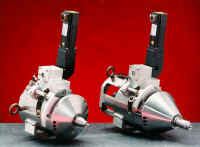
    To overcome these drawbacks, a NASA Marshall Space Flight Center welding engineer helped design an automatic retractable pin tool that uses a computer-controlled motor to automatically retract the pin into the shoulder of the tool at the end of the weld preventing keyholes. This design allows the pin angle and length to be adjusted for changes in material thickness and results in a smooth hole closure at the end of the weld.

    The possible application of FSW in construction area is as following:

    Frictionstirwelding
    • Construction Equipment (truck bodies, mobile cranes)
    • Transportation including railroad industry (high speed trains, underground carriages)
    • Bridge (aluminum components)
    • Panels made from aluminum, copper or titanium
    • Window frames
    • Heat exchangers and air conditioners
    • Pipe fabrication, etc.

    The Benefits
    • Diverse materials: Welds a wide range of alloys, including previously un-weldable (and possibly composite materials)
    • Durable joints: Provides twice the fatigue resistance of fusion welds and no keyholes
    • Versatile welds: Welds in all positions and creates straight or complex-shape welds
    • Retained material properties: Minimizes material distortion
    • Safe operation: Does not create hazards such as welding fumes, radiation, high voltage, liquid metals, or arcing
    • No keyholes: Pin is retracted automatically at end of weld
    • Tapered-thickness weld joints: Pin maintains full penetration

    Labels: ,

    Friday, September 11, 2009

    Arc Welding Hazards

    Accident Hazards

  • Injuries due to sparks or hot metal falling into folds of rolled up sleeves and pant- cuffs or work boots.

  • Electric shock from excess moisture (e.g. perspiration or wet conditions) and contact with metal parts which are "electrically hot".

  • Fire or explosion due to extreme temperatures (up to 10,000F) from welding sparks coming into contact with flammable materials (e.g. coatings of metals, gasoline, oil, paint, thinner, wood, cardboard, paper, acetylene, hydrogen, etc.)

  • Falls during work on ladders, above ground, and in confined spaces.

  • Eye and face injuries from flying particles, molten metal, liquid chemicals, acids or caustic liquids, or chemical gasses or vapors.

  • Physical Hazards

  • Exposure to high noise levels from arc welding equipment, power sources and processes.

  • Exposure to ultraviolet (UV) radiation resulting in skin burns and skin cancer. "Welder's flash"(brief exposure to UV radiation) may result in temporary swelling and fluid excretion of the eye or temporary blindness.

  • Cataracts from chronic exposure to UV radiation.

  • Irritation of lungs due to heat and UV radiation.

  • Chemical Hazards

  • Exposure to metal fumes causing metal fume fever (temporary illness similar to flu) from zinc fumes.

  • Bronchitis and lung fibrosis due to mineral dusts or fumes.

  • Potential exposure to manganese, cadmium, shielding bases (argon, helium and carbon dioxide) chromium, nickel, steel and other metals.

  • Pulmonary granulomatous disease due to chronic beryllium exposure.

  • Biological Hazards

  • No significant biological exposures expected.

  • Ergonomic, psychosocial and organizational factors

  • Back pain and other musculoskeletal problems resulting from fatigue due to standing for long periods, sprains due to lifting of heavy machinery or metal products and cramping due to working in vertical, horizontal or overhead positions.

  • Wrist, elbow or shoulder joint pain due to repetitive motion while feeding material.
  • Labels: ,

    Thursday, September 10, 2009

    Plasma Arc Cutter Operating Procedures


  • To activate the plasma arc cutter make sure the air pressure is sufficiently around 70 p.s.i. for most plasma arc cutter units and the ground clamp is attached to the work piece.

  • Turn the plasma arc cutter on and adjust the amperage the manufacturers specifications for the thickness of metal to be cut.

  • Position the shielding cup over the metal, press the igniter button and allow the arc to become established. Next, move the arc over the cut line and make the cut.

  • The thicker the metal the slower the travel speed must be to get a good cut and vice versa. The quality of the cut usually decreases as the metal thickness increases and the travel speed decreases.

  • A guide bar may be used to help achieve good straight cuts.

  • The shielding cup and constricting nozzle should be held approximately 1/8" to 1/4" above the metal being cut. The operator should avoid dragging the constricting nozzle and shielding cup on the metal when making the cut unless they are specifically designed to touch the base metal while cutting.

  • Always make cuts on the waste side of the cut line.

  • Avoid cutting with the plasma arc cutter in damp or wet locations. The hazards of electrical stock greatly increased.

  • If plasma arc cutting over an open barrel with a grate be aware that the fume plume will be directed back toward the operator. Avoid this condition if at all possible, otherwise limit the exposure to fumes to short duration's.

  • Cuts with the plasma arc cutter may be made by moving forward, backward, or sideways. Determine which direction is easiest for you and use that procedure as often as possible.

  • Always move the plasma arc cutter (PAC) as fast as possible when making a cut. This increases time efficiency , improves the cut quality, and reduces the build up of dross.

  • Compressed air used in plasma arc cutter should be dry or the cutter will not yield a quality cut or it not cut at all. An auxiliary air filter may be place in the compressed air line to condition the air for a plasma arc cutter.

  • Always turn the plasma arc cutter off before laying the torch down and leaving the work area.

  • If the quality of the cut deteriorates to an unacceptable level either the constricting nozzle, the electrode, or both may need to be changed. The electrode on most plasma arc cutter will have a life of about twice the life of the constriction nozzle. Keep a supply of constricting nozzles and electrodes on hand as they deteriorate quickly during continuous use. Turn the plasma arc cutter off to put on replacement parts.

  • Keep the plasma arc cutter torch leads and ground lead stored so they will not be cut or damaged when not in use.
  • Labels: , ,

    Wednesday, September 9, 2009

    Plasma Arc Cutter Safety


    • Wear protective clothing when using the plasma arc cutter. Clothing should be wool or cotton, long sleeves, leather shoes (High Top), gauntlet gloves and leather apron.

    • Never wear synthetic clothing when using the plasma arc cutter, many synthetics are highly flammable.

    • Always wear industrial quality eye protection a #5 shaded lens is minimum for the plasma arc cutter process. The shaded lens needed to adequately protect he eyes varies by the thickness of the metal being cut and the intensity of the arc required to make the cut. Follow the manufacturers recommendation for selecting an appropriate shaded lens for given plasma arc cut.

    • Make sure that work area is well ventilated when using the plasma arc cutter. The plasma arc cutter process generates lots of fumes and therefore must be well ventilated.

    • The operator should position himself/herself so there will be minimum exposure o fumes during the cutting process.

    • Use a cutting table which has a down draft to capture fumes. A cutting table with water filtration is also recommended for plasma arc cutting.

    • Never use the plasma arc cutter in areas where combustible or explosive gases or materials are located.

    • Chlorinated solvents and cleaner vapors in the presence of plasma arc cutter generates a toxic phosgene gas. Avoid plasma arc cutting use in areas which house chlorinated solvents and cleaners.

    • Never touch any parts on the plasma arc cutter that are electrically connected. The plasma arc cutter uses high amperage and produces high voltage which can cause severe or fatal electrical shock.

    • Disconnect the electrical power before performing any service or repair on the plasma arc cutter.

    • Do not use the plasma arc cutter to cut on containers that have held combustible materials.

    • Hydrogen gas may be formed and trapped when cutting aluminum in the presence of water. Trapped hydrogen gas in the presence of an are will ignite and explode, make sure fumes are well ventilated when cutting aluminum.

    • Hearing protection should be worn when operating the plasma arc cutter.

    • Make sure that others in the work area are protected from the plasma arc cutter arc rays and fumes.

    • Use pliers or tongs to handle hot metals cut by the plasma arc cutter. Cool and store hot metal before leaving the work area.

    Labels: ,

    Friday, September 4, 2009

    Butt Joint

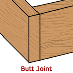
    Butt JointFor light materials the square-edge butt joint is the easiest to prepare and can be welded without filler rod. It consists of “butting” two pieces of metal up against one another (no overlapping) and then welding along the seam between them. If the weld is to be made without filler rod, extreme care must be taken to avoid burning through the metal.


    The single-V butt joint is preferable on material ranging in thickness from 3/8” to 1/2” in order to secure complete penetration. It is prepared like a regular butt joint except that the top edge of each piece is chamfered in order to reduced the area of contact between the two. The included angle of the V formed by the chamfering should be approximately 60° with a depth of about 1/8” to 1/4”.

    weldingjoints

    The double-V butt joint is needed when the metal exceeds 1/2” thickness and the design is such that the weld can be made on both sides. This is like a single-V joint except that both the top and the bottom edges of the pieces are chamfered, and welding is performed on both sides. With a double V there is greater assurance that penetration will be complete.

    Labels: ,

    Thursday, September 3, 2009

    Spot Welder

    spotwelding
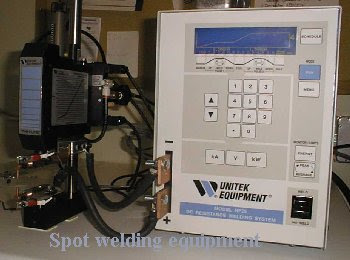
    Resistance spot welding delivers an electric current to join materials through heating. The four stages in the welding process are squeeze, weld, hold, and release. During the first stage the materials are brought into contact through physical force. The welding current is then delivered and the materials are brought to their plastic state. By holding the materials together after the weld pulse the weld nugget solidifies and then the force can be released. The more control a welding instrument provides over each of these stages the greater the quality of weld that can be produced. Ideally, an instrument allows the operator to program weld cycles with specified currents and pressures.

    When executing a typical single-pulse weld, the current travels through the points of initial contact at the junction. Due to the presence of the oxide layers at this interface the current will flow through the peaks created by the oxide layer forming a brittle weld between those peaks. In a dual pulse spot weld, a pre-pulse, prior to the weld pulse removes the oxide layer from the materials and increases surface contact to create an effective weld.

    Variables that must be controlled by spot-welding instruments are energy, time, and physical force. The new High-Frequency Direct Current inverter (HFDC) systems provide highly programmable instruments that use feedback loops to accurately deliver the specifications of a welding cycle. Controlling the position of the welding tips and the physical force applied to the weld site, are necessary to achieve quality welds. Hand-held weld heads rely on operators' ability to choose, and maintain throughout the weld cycle, the position of the tips and the level of the force. Technological improvements such as air-actuated electrodes control the force with which materials are brought into contact, reduce operator variability and increase reproducibility of quality welds. The required force is set by the operator and the weld-head is driven by an air cylinder that maintains the preset force. Application of the required force as materials change volume during the weld cycle is central to the production of strong spot-welds. Another advantage of the air-actuated weld held is the decrease in crystal damage because the polished crystal face is not placed down face down during welding. The operator orients the crystal and other metal between the tips of the electrodes and uses the bi-level foot switch to apply force to the materials and then deliver the weld cycle.

    Labels: , ,